I suspect this subject has been named Systems Engineering to provide the E in STEM. To its credit it may provide an opportunity for a student to determine if she/he has any interest in designing or constructing actual things. It's a good concept, just a pity it's not called System Design as it's not actually engineering which is more closely linked to physics and mathematics.
What is Engineering? Physicists like saying that engineering is simply applied physics, which makes as much sense as saying writing a novel is simply applied grammar. Some people can be bilingual, so to speak, for example, Richard Hamming was a mathematician who was also very comfortable doing engineering. He said that given a problem, an engineer can always find a solution, in contrast a mathematician given a problem may prove that the problem does not even have a solution. The engineer’s toolbox is much more extensive than the mathematician’s since the engineer will use mathematics when applicable to find a solution to her/his problem, but a mathematician will never use engineering to solve his problem.
Systems Engineering approaches its subject material with a broad brush. A perusal of past examination papers suggests that since 2019, that is, for 2022 and 2021 there has been a relaxation of demand (or colloquially expressed, a dumbing down) in the examination questions. Consider the 2019 paper Section B, Q 4. Students were required to understand in some detail the operation of a bridge rectifier, a capacitor, a transistor and a zener diode. At the most, 1% of the students gained full marks. I suspect we will not see the like of that question again. It would not be feasible to teach each topic to the level required to answer question 4. Thus instead of the V/I characteristics of a zener diode we now have the resistor colour code.
The examination content is increasingly predictable, so those students wishing to do well in the examination should be able to do so by working through past examination papers.
Unfortunately, as in Physics, we see the examiners make use of the centimetre unit. Here is a prediction; if you proceed into an engineering or trades career you will never use a centimetre again. The ‘small’ unit of length in the making-actual-things world is the millimetre. You will also find yourself using “engineering“ rather than “scientific” exponent notation. The rule for engineering notation is that the exponent is always expressed as a multiple of 3, this technique adds simplification and the reassignment of units. For example the speed of light is written as (approximately) 300 x 106 ms-1 rather than 3.0 x 10⁸ ms-1, or as 300 x 103 kms-1 rather than 3.0 x 10⁵ kms-1. I suspect you'll need to use it for a time to grow into it and to appreciate its advantages.
The winner is (drum roll) the 2017 Examination Section B Q 6a. Seriously, this is an excellent question, no formula plugging, just a basic understanding of levers and creative thinking. It even uses the right units! It actually is engineering.
Supplier of highly developed electronic assembled boards – computer on a board, that sort of stuff.
A good range of project ready items, in general terms directed towards robotics. Reliable Australian suppler, reasonable prices and excellent delivery.
DigiKey, www.digikey.com/
A very professional and comprehensive electronic component supplier. Excellent supporting material. Small quantities of minor items are no problem. Free postage for moderate orders. (Perhaps make up a group order.)
The way to buy stuff on Ebay is work with local registered suppliers, else you could end up watching your SAT life tick by.
Short run PCBs. Excellent quality, good price, good service. A Chinese company so you need to plan ahead not to be embarrassed by delivery delays. If you know of an Australian company with similar PCB service, please email me.
Extensive range of electronic components, local distribution centre.
Extensive range of electronic components including passive components and training kits.
Jaycar Electronics supplies electronics kits, components, semiconductors, enclosures, batteries & chargers, power supplies, test equipment, tools, speakers, computer accessories, lighting, and other items. Stores throughout Victoria and an effective online ordering system. The catalogue is a comprehensive list of what's available – a class copy could prove very useful.
A very extensive range of industrial standard electronic equipment including passive components and instrumentation.
A high end 'experimenter' supplier. A extensive range of electronic components and support items. Well worth a look.
Extensive range of electronic components, local distribution centre. Good to work with.
A high end 'experimenter' supplier. A good range of breakout boards and hardware. Items are well documented and designed to be integrated readily into your product. Take care, the prices are in USD and the postage is costly so purchases can be more expensive than you first expected.
Wagner Online has an extraordinary range of electronic related products ranging from 0.25 W resistors to surveillance cameras. An excellent online catalogue is available.
A professional level PCB design package. A freeware version with 500 pin, 2 signal layer limit is available.
An excellent CAD package available to run under an extensive range of operating systems. Available as a ready to run free version without full features.
The two fundamental laws of circuit analysis are:
Kirchhoff's current law (KCL) states that the sum of the currents flowing into a node is zero.
Kirchhoff's voltage law (KVL) states that in any closed loop in a circuit, the sum of voltages is zero.
Currents flow into nodes and out of nodes. Voltages occur between nodes. Nodes on a circuit diagram are readily defined with a highlighter pen. Look at the diagram to the right, 3 nodes have been defined (by convention the ground or zero volt node is called the reference node and assigned the number 0). Nodes are bounded by components, run your pen along connections until you reach a component. Really, it's easier to do than to explain, try it. There are 4 more nodes to identify, one of which is a "simple node" (you'll know it when you find it).
The formal expression of KCL requires that the currents flowing out of the node are signed negative. An alternate expression of the law states that the sum of the currents flowing into a node equals the sum of currents flowing out of a node. (If you think of the currents as litres of water, cars at an intersection, billiard balls along pipes or whatever then the law becomes self-evident.)
An alternate expression of KVL is that the sum of the voltages along a sequence of nodes connecting one end of the voltage supply to the other is equal to the voltage supply.
For linear resistances R = V/I R, ohms; V, volts; I, ampere. Not all devices are linear, that is, if you plot I against V you do not get a straight line for those devices. Consider an incandescent globe, the filament is tungsten which normally presents a linear resistance, and certainly at low voltages a globe has linear characteristics. However as the voltage is increased the temperature of the filament increases and the current does not change in proportion to voltage. Most semiconductor devices, LEDs, diodes, zener diodes, photo diodes, transistors, are non-linear.
If you use kΩ as your base unit of resistance, mA as your base unit of current and maintain V as your base unit of voltage, then Ohm's Law applies without modification. For example a 1.5 kΩ resistor across a 3.0 V battery will carry a current of 3.0/1.5 = 2.0 mA.
Resistors dissipate power and along with resistance and accuracy, the power rating should be considered. If, for example, you are using a series resistor to operate a 6 volt 18 watt globe from a 12 volt supply at its rated voltage the resistor will be dissipating 18 watts. Such a resistor will be large and relatively expensive.
I cannot get my head around the casual inclusion of capacitance in this subject. If you have a specific question about capacitors please email me at the email contact at the bottom of this page, Harlan.
Just bone up on it for the examination. This website may be of some use.
In workplaces where people frequently use the resistor colour code they actually read the values rather than 'sounding them out' like a prep student following the text. They see red,red,red and say without hesitation 2.2 kilohm. (Actually they probably say "two-kay-two" as this, 2k2, is how it usually appears on a circuit diagram. This prefix substitution technique is used to avoid the lost decimal point.) There are interesting (well, for some people) aspects to resistor values. Start at this website if you have an interest.
The items in the title above (and many more) are all covered by a fundamental concept of physics – the Principle of Virtual Work, which can be expressed (at the risk of over-simplification) for mechanical situations as:
(displacement in) X (force in) = (displacement out) X (force out).
The displacement may be linear, angular or (with attention to units) a combination of linear and angular.
The principle is useful for situations where the relationship between input and output displacements can be established (by whatever means) but the relationship between the input and output forces is unknown. Consider for example a chain hoist, a user pulls down on a chain and a combination of gears and pulleys raises the load. If experimentation establishes that a 1000 mm displacement of the input chain moves the load hook by 25 mm, what is the maximum load a 50 kg person could lift?
If we agree (for simplification) that the ratio of masses will be equal to the ratio of forces, then the maximum load a 50 kg person can lift by using a her body weight will be (1000/25) X 50 = 2000 kg. The significant thing is that we could make this determination without any knowledge of the internal design of the hoist.
In classic parlance there are three classes of levers. These classes are presented in the standard texts. You need to know the classification for the examination.
In practice it's not always clear, nor does it matter what class a particular lever is operating as. Is it the load compressing the spring (class 2 say) or is the spring supporting the load (class 3)? Don't worry, outside of the examination situation, no one will ever ask you.
The diagrams at the start of the 2020 and 2021 examinations present with clarity the concept of perpendicular distance on the force line of action from the fulcrum. In some instances this formal ratio is matched by the ratio of measurements along the lever.
The pulley applications fall into two broad applications: transmission systems and hoists. The flexible component may be cord, belt or chain.
A standard bicycle is resting on the ground supported upright but without any constraint on its movement forward and back. The right pedal is at the bottom of its stroke. A person kneeling beside the bike pushes back on the pedal, that is, she attempts to rotate the crank in a clockwise direction which would normally move the bicycle forward. What actually happens?. Provide an explanation.
An excellent learning aid for the transmission application of pulleys/gears is the conventional multiple gear bicycle. If you have the opportunity set it upright with the rear wheel clear of the ground and with the chain side towards you (that is, with the rear wheel to your left). Do stuff like select the lowest gear and count the number of rotations of the rear wheel for one rotation of the crank. Do the same exercise for the highest gear. Fiddle about until you are confident that you can answer the typical examination question on pulleys/gears used for transmission without consulting the Formula Sheet.
The chain runs from the front sprocket, or "chain wheel", around the two idle sprockets on the rear derailleur then round the rear sprocket (on the "cassette", "cog set", "sprocket set" or traditionally "block") and back to the chain wheel.
Sprockets that do not transfer power to or from the chain are known as idle sprockets (or pulleys). Note which way (CW, ACW) each of the 4 sprockets rotate and convince yourself you could do similar stuff for an examination question.
Note also that in a transmission application the tension in the chain/cord/belt differs between spans.
The standard question on hoist pulley systems usually requires the student to determine the force ratio (aka the mechanical advantage) of a system. Given that all the pulleys are free running the key facts are that the tension in the cord is the same throughout the active length and that the relative sizes of the pulleys is a practical consideration, not a theoretical one.
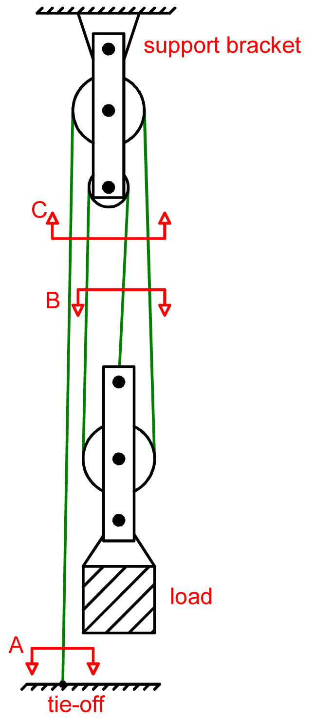
The diagram on the right shows a conventional hoist configuration. The load has been hoisted and tied off. The slices A, B and C single out the tie-off point, the load and the support bracket respectively. If we take the tension in the cord to be T newtons then by inspection we can see that the force acting on the tie-off point is T newtons, the force supporting the load is 3T newtons and the force acting on the support bracket is 4T newtons. The (so called) mechanical advantage of the system is {output force)/(input force), that is (3T)/(T) = 3. If the load weighs 600 newton, then T = 200 newton, the force on the tie-off point is 200 newton and the force on the support bracket is 800 newton.
The hydraulics in this unit seem straightforward. The force on, or delivered by a piston is proportional to the area of the piston or the square of its diameter. Hence, for a 2 piston configuration the ratio of forces will be equal to the ratio of areas or the square of the ratio of diameters. The ratio of displacements will be the inverse of the force ratio.
I don't know any way of answering examination questions about gears other than by understanding gears, there are just too many variations for simple formula plugging. Perhaps a professionally written textbox could help, or maybe the school can provide some gear sets to experiment with? The majority of items such a with small electric motors will have gears. A small motor needs to operate at high angular speed to achieve high power. The torque is limited by the magnets used in the motor's construction and the limitations on the operating current. So more power (the product of torque and speed) requires more speed and matching that power to an application requires a gearbox. The first gear in a gear train is typically mounted on the output shaft of the motor and it is smaller than the spur gear it drives and is known as a pinion.
The diagram for Question 10 Section A, Examination 2021 is shown on the right. Industry notation for gearboxes uses the terms input shaft and output shaft.
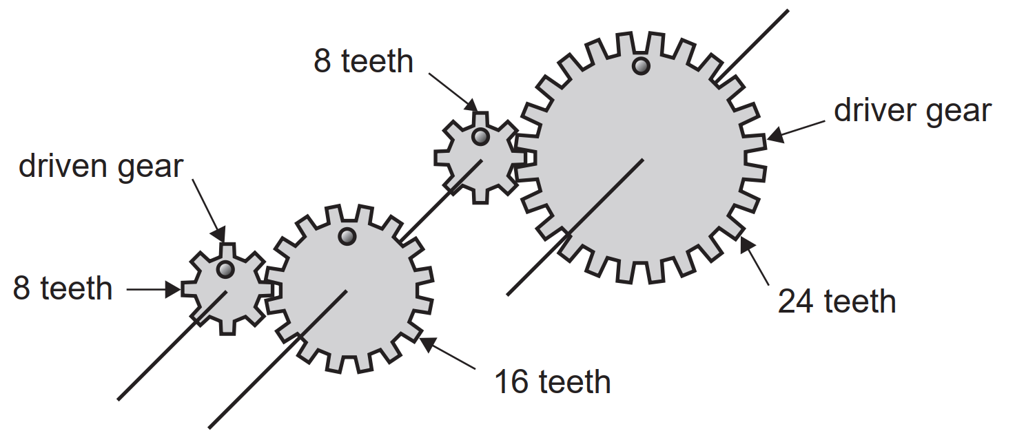
For example in a conventional car the input shaft of the gearbox is connected to the motor and the output shaft is (ultimately) connected to the drive wheels.
The gear ratio is determined by dividing the number of teeth on the driven (output) gear by the number of teeth on the driving (input) gear.
It is the ratio of torques, not of speeds. Thus a conventional car manual gear box may have a "first gear" ratio of 18 (to provide high initial torque) and a "top gear" ratio of 1.0 to enable highway speeds.
(The gear ratio for the examination question is 1/6 expressed as 1 : 6.)
As an exercise assume a direction of rotation for any gear in the figure and then determine the direction of rotation for each of the other gears.
The diagram for Question 10 Section B, Examination 2020 is shown on the right. It "shows part of a simple steering system using a worm drive and levers to change the direction of the front wheels on a car". This question is truly bizarre, it falls into the same category of failed "real world" questions as those discussed in the VCE-Circus "Physics Past Examinations" page.
How is it intended that this item should actually work? It seems that the "spur gear" can rotate, as the examiner asks If the spur gear had seven working teeth, with only one tooth meshing with the worm drive at any time, what is the gearbox ratio? The answer is given as 7:1 consistent with a rotating spur gear. If the spur gear can rotate it cannot provide any force to the linkage components – in fact there would be no forces anywhere, just a frustrated driver. If the spur gear was fixed to the linkage, why use a complete spur gear at all? Then the gearbox ratio would be considerably higher than 7:1.
Worm drives (like other threaded items) can be produced as single and multiple start thread items. Wind a string neatly round a pencil several times and you have a reasonable representation of a single start thread. Bolts and screws are generally single start threaded. Now take another piece of string (a different colour preferably) and wind it turn for turn between the turns of the first string. You now have a reasonable representation of a two start thread. If you have a single start worm and gear configuration, then for each turn of the worm the gear moves by one tooth. If it were a two start worm then for each turn of the worm the gear would move by two teeth. I guess that the examiner's comment only one tooth meshing with the worm drive at any time was some oblique indication that it was a single start worm. (The 2020 diagram shows a two start worm, see Question 14 Section B 2021 for an example of a single start worm.)
In a pulley system idle pulleys may be used to manage the passage of a belt, for tensioning or to guide the belt clear of other objects. Idle gears may be used in gear systems to reverse the direction of rotation (a classic way of implementing a reverse gear in motor vehicles) or for layout management. Question 14 Section B 2021 shows a neat example. Note that the number of teeth on the idle gear does not affect the gear ratio.
The Control Systems Primer is a downloadable PDF file providing an introduction to feedback systems.
This primer discusses Levers, pulleys and gears and the Principle of Virtual Work.
This primer has some introductory discussion about some basic electronic components and instruments.
There is good support material for reading circuit diagrams at this SmartFun site.
The selection of a SAT project is going to be determined to a great extent by what equipment is on hand and the technical interests and experience of the student. There are a couple of ideas below, also you may find something on the Physics Investigation page that could be adapted. In order to add some formality to your investigation you may need to express the topic as "A method of demonstrating the basic techniques of XXX". For example, the noughts and crosses investigation could have the title "A system to demonstrate the fundamentals of interactive robotics".
Problem: How do we introduce low level AI, algorithms and robotics at an early education level?
The version in my head uses a pick-and-place device to put tokens marked X on the playing board. The human's tokens are marked 0. The human starts, the robot places its token to counter the human move. The game continues in the usual manner.
The human can draw (because it has first move), but never win (the robot is too smart to be caught). The board/token design will require care. The robot will need to sense the arrival an 0 token and remember where it has placed its own token so that it has an image of the board in memory and can determine its next move. One (there will others) approach would be to have a reed relay at each square and magnet in each 0 token. Placing a 0 token on a square will close the reed switch.
The task sensibly could be done by a smart person or as a team project with members assigned mechanical, interface and computing sub-tasks.
Problem: In order to understand Special Relativity a firm understanding of moving reference frames is required. This demonstration configuration works towards this end.
In classical physics the Doppler effect is the variation in frequency that occurs between a source and sensor travelling at different velocities through the transmission medium. The oft quoted example is a train sounding a warning as it approaches, crosses and departs from an railway crossing. To a person at the crossing as the train approaches the frequency of the note sounds high, as the train departs from the crossing the frequency lowers. A corresponding (inverse) variation in wavelength occurs.
The (not to scale!) diagram above shows a possible configuration for a model to investigate the Doppler effect. Designing it would effectively be an instrumentation exercise – the choice and interconnection of transducers and equipment to acquire data. Students with some experience in 'hobby' level electronics might be a sound choice. The vehicle is a model car (radio controlled and/or with microcontroller smarts) fitted with a speaker producing an audio frequency. The vehicle speed is determined by timing it between two markers, T0 and T1. M0 and M1 are audio microphones, two are required to measure wavelength. Data is stored on a two channel digital oscilloscope.
Working figures are:- transmitted frequency, 1kHz; vehicle speed, 3 ms-1. These values would result in a frequency of 1.016 kHz at the stationary sensors.
Problem: The traditional mechanical music box can play but one tune. Can an electronic music box do better than that? (A fundamental requirement of a music box is that the music is produced mechanically.)
Simple 8 bar xylophones (wooden bars) or glockenspiels (metal bars) are available as introductory musical instruments. Small solenoids could be interfaced (beware driving inductive loads – lookup "protection diodes") to the microcontroller which holds a set of coded tunes. All up it would be a nice blend of mechanical design, electronic design and programming.
Preamble: There are a wide range of sensors used in manufacture. One application for sensors is in the selection, and grading of items. The items are loaded onto a transmission belt and a sensor reads a critical parameter, a determination is made and the item is fed to the right or the left. Problem: Make a rig to demonstrate this principle in the class room.
Let’s say for the demonstration you are going to sort a stream of black and white plastic discs into two bins. You'll need to set up a suitable transmission belt, devise an optical sensor to determine the colour, work out a means of directing the discs to the appropriate bin and program a microcontroller to handle the smarts.
Preamble: Trackers for solar panel arrays fall into two broad classes – single axis trackers and two axis trackers. The mechanics of two axis trackers are considerably more complex than single axis trackers and the expense may not be justified when the alternative is simply using additional solar panels. The use of single solar axis trackers in solar farms is mechanically attractive because the individual arrays in a row of solar arrays may be mounted on a common shaft. This shaft can rotated to the optimum angle by a mechanism at the end(s) of the row. The sketch at the right shows a single reference controlling two rows of arrays by a communication link.
In fact with a suitable communication link a single reference (which might be relatively small) could serve an entire solar farm, even if the farm consisted of scattered blocks of arrays.
The design of a suitable communication method and the building of a scale demonstration model (perhaps using stepper motors, and not necessarily with actual solar panels) could make an excellent investigation project.
Preamble: A fibre optic cable kit (https://i-fiberoptics.com/pdf/if-e10.pdf) is available from a number of suppliers. (See for example Digikey, https://www.digikey.com.au/en/products/detail/industrial-fiber-optics/IF-E10/3724)
There is scope for designing a digitally multiplexed fibre optical perhaps using the serial i/o on a small single board computer at each end. An effective demonstration would require two different audio sources at the transmitter end that are presented separated at the receiver end.
Examination specifications (including link to SD) (VCAA link accessed 04/10/2025)
Sample questions (May 2019) (VCAA link accessed 04/10/2025)
Formula sheet (November 2024) (VCAA link accessed 04/10/2025)
2024 Examination (VCAA link accessed 04/10/2025)
2024 Examination Report (VCAA link accessed 04/10/2025)
2023 Examination (VCAA link accessed 04/10/2025)
2023 Examination Report (VCAA link accessed 04/10/2025)
2022 Examination (VCAA link accessed 04/10/2025)
2022 Examination Report (VCAA link accessed 02/02/2025)
2021 Examination (VCAA link accessed 04/10/2025)
2021 Examination Report (VCAA link accessed 04/10/2025)
2020 Examination (VCAA link accessed 18/08/2022)
2020 Examination Report (VCAA link accessed 04/10/2025)
2019 Examination (VCAA link accessed 04/10/2025)
2019 Examination Report (VCAA link accessed 04/10/2025)
2018 Examination (VCAA link accessed 18/08/2022)
2018 Examination Report (VCAA link accessed 04/10/2025)
2017 Examination (VCAA link accessed 04/10/2025)
2017 Examination Report (VCAA link accessed 04/10/2025)